

 Download
 Buy
BuyFirebird Maestro online Help
| Prev | Return to chapter overview | Next |
Schema Designer
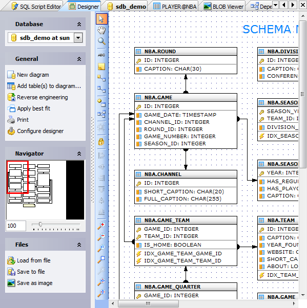
Schema Designer allows you to create physical Entity Relationship Diagram that will represent objects in your Firebird database. A diagram represents the tables of your database and the relationships between them. The tool is intended for reverse engineering and database modification in an easy and powerful way. It helps you to simplify database maintenance.
A diagram of your database can help you define operational aspects of your application logic that you might otherwise overlook. Also, a well-defined data diagram that accurately represents your tasks can be helpful in orienting employees to goals and operations. The data diagram can also serve as an invaluable communications tool for both internal and external constituents.
Below you can find answers for the following questions:
See also: Designer Navigation bar, Schema Designer Toolbox.
You can add an existing Firebird table to the diagram using popup menu in the working area, or with the corresponding link on the Navigation bar.
To create a new table, use the appropriate item of the popup menu in the working area. The table will be created in the current database.
Tables also may be dragged on the diagram from Explorer and the similar to Explorer tools like Object Manager and Object Browser.
Moreover, Designer provides you with a possibility to represent all the tables and relationships existing in the database automatically (the Reverse engineering link of the Navigation bar). At that the database contents will be represented on a diagram in the most compact and vivid manner.
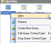
All the diagram objects are available for editing. Just double click the object (table or relationship) to view/edit its properties within the corresponding editor.
Adding a relationship between tables
At adding to a diagram tables that reference on each other, the relationships between tables are represented automatically. The Schema Designer tool also allows you to add new foreign keys to the diagram tables. Thereto you can do the following.
Select a table (child table)
| • | Use the Create new... item of the popup menu to launch Foreign Key Properties window. |
| • | Specify there properties of the relationship been created. |
Moreover you can add a reference graphically:
| • | Choose the Create relation tool on the Toolbox. Your mouse cursor will change its appearance. |
| • | Then click on the table (child table) that will have foreign key and then click on the second table (parent table) whose primary key will be referred by the new foreign key. |
| • | Specify properties of the relationship been created in the Foreign Key Properties window. |
With the Create new… item of the popup menu you can also add a new field, an index, a trigger, etc. to the selected table. For more information about object properties see: Field Editor, Index Editor, Create Trigger Wizard.
Deleting of the diagram objects
To hide a table (several tables) or a relationship between tables, select the objects and click Remove selection link of the popup menu or Navigation bar. You can also use the Del key for this purpose.
It’s also possible to physically delete a table/foreign key from the database: just select the object to delete and use the appropriate item of the popup menu.
Editing of a diagram appearance
Movement of a table/several tables along the diagram is realized with dragging or pressing Ctrl+arrows. You can use Shift+arrows to change width/height of table/several tables representation.
Designer also allows you to edit shape of the line representing foreign key relations/logical relations. In order to break the line you should
| • | Select the relationship. |
| • | Press Ctrl and click on the necessary line section to create a new node. |
| • | Position the node by dragging. |
You can also delete a node on the line. Thereto
| • | Select the relationship. |
| • | Press Alt and click the node to delete. In that case the near nodes will be united by a straight line. |
| Prev | Return to chapter overview | Next |